Energy generation produces large quantities of hot exhaust gas. Heat exchangers and evaporators can recover part of this thermal energy. In a heat exchanger, heat is transferred through a separating wall from a hotter medium to a colder one.
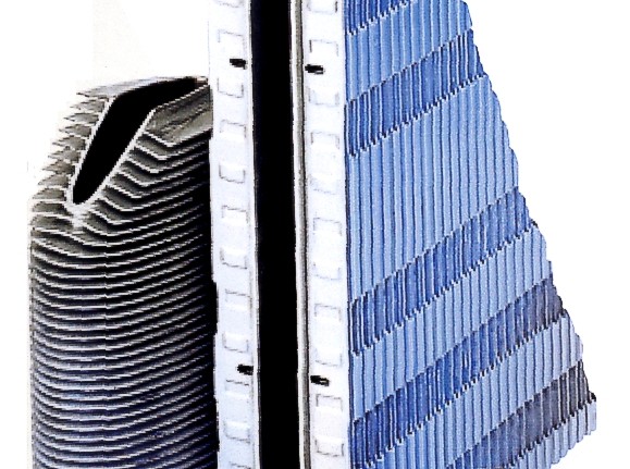
Many heat exchangers use fins to increase the heat-transfer area. Although geometries vary widely between applications, the fundamental design challenge remains the same: achieve high heat transfer while keeping the pressure drop as low as possible.
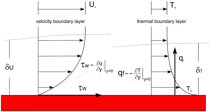
Both heat transfer and pressure loss are strongly influenced by the boundary layers along the walls of the flow passages formed by the fins. Because of the no-slip condition, fluid velocity is zero at the wall and increases through the velocity boundary layer towards the main flow. The velocity gradient at the wall determines the wall shear stress and is therefore directly related to frictional losses. In the thermal boundary layer, the temperature gradient at the wall determines the local heat flux.
Measuring these local boundary-layer processes inside a compact heat exchanger is extremely difficult. Experimental development therefore often relies on global quantities such as total pressure drop and inlet and outlet temperatures at different operating conditions. These measurements describe overall performance, but provide much less information about the local causes of excessive losses or insufficient heat transfer.
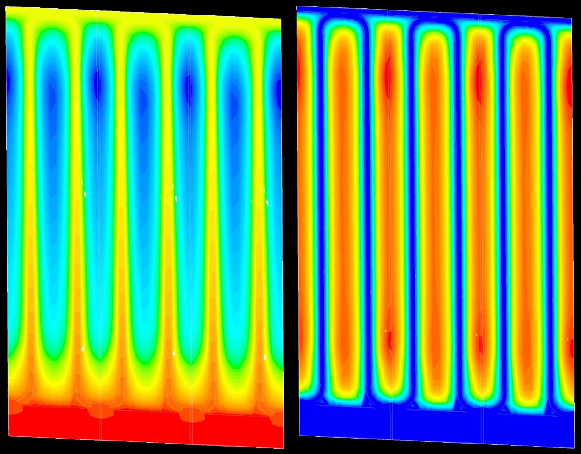
CFD simulations make these local velocity and temperature fields visible. By analysing the flow between individual fins, regions responsible for increased pressure loss or reduced heat transfer can be identified, allowing the geometry to be optimised in a targeted manner.