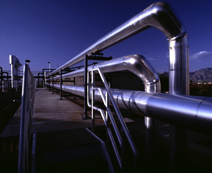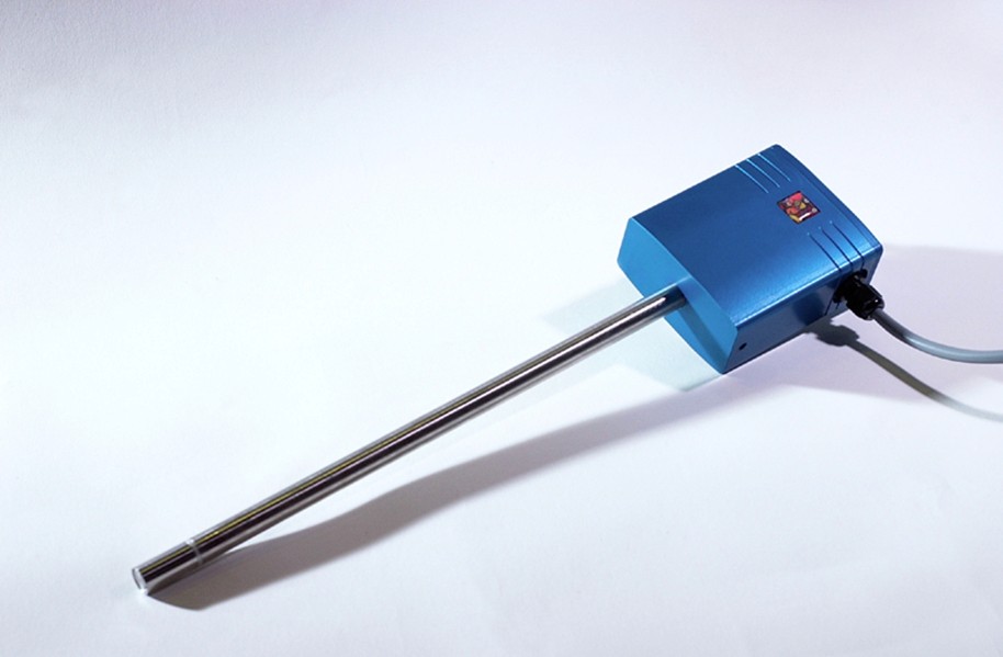
A wide range of sensor technologies is available for measuring gas volume flow in pipelines. Some sensors use a heated element and derive a measurement signal from the local heat transfer, which can be related to the local flow velocity.
When volume flow is derived from a local velocity measurement, the position of the sensor in the pipe is crucial. FlowMotion therefore calculated the flow through various pipe components for a manufacturer of measurement systems and investigated how bends, changes in cross-section and other disturbances affect the velocity profile.
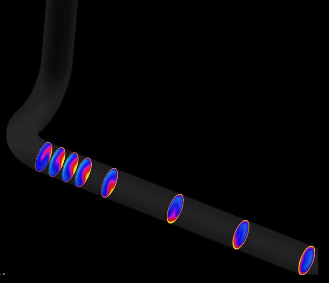
Because of the no-slip condition, velocity is zero directly at the pipe wall and increases towards the centre, producing a velocity profile across the pipe. After a bend, branch or other geometric disturbance, this profile does not immediately return to a fully developed state. The required development length depends on factors including the geometry and the flow regime.
For an accurate volume-flow measurement, the relationship between the locally measured velocity and the cross-sectional mean velocity must be known. Even a small percentage error can have substantial financial consequences when large gas volume flows are involved.
CFD was therefore used to determine how the velocity profile redevelops downstream of different pipe components. For the configurations investigated, the calculations indicated that on average at least about 40 pipe diameters were required before the profile was sufficiently developed again.
The CFD results can be used in two ways: to position the sensor where the measurement error is minimised, or to use the calculated velocity distribution when converting a local velocity measurement into volume flow. The latter is particularly useful when installation constraints do not allow a sufficiently long straight pipe section.